Author: Ir. Dr. Justin LAI Woon Fatt | 30 May, 2026
INTRODUCTION
A fire hydrant is a part of a pipework system connected directly to the public water mains. Its primary function is to provide water to the Fire and Rescue Department Malaysia (BOMBA) firefighters through connected hoses for firefighting operations. Fire engines draw water from the hydrant system and discharge it through hoses during firefighting operations. There are two common types of hydrant water supply systems, namely non-pressurised (direct) systems, and pressurised (pumped) systems.
DESIGN STANDARDS
Under By-Law 225 (2) of Uniform Building By-Laws (UBBL) 1984 (Amendment 2021), at least one fire hydrant shall be provided for every building. The hydrant shall be located within 30 m of the building entrance or breeching inlet. In addition, the hydrant pipework should be MS 1489 Part 2 (Wet and Dry Firefighting Mains) compliant, while the fire hydrant itself shall comply with MS 1395 (Specification for Pillar Hydrants). Furthermore, fire hydrants shall be spaced not more than 90 m apart.
HYDRANT OUTLETS
To protect firefighters from falling debris, hydrants should be installed at least 6 m away from tall buildings. Generally, fire hydrants are installed along access roads with a minimum width of 6 m and capable of accommodating a 26-tonne fire appliance load [1]. Hydrant outlets are typically of the twin-outlet pillar type complete with an underground sluice valve.
Meanwhile, within private premises, hydrant outlets may also be of the landing valve type without underground sluice valves. In such cases, a 30 m long, 65 mm diameter canvas hose complete with instantaneous couplings and nozzle is usually provided within a hose cabinet adjacent to the hydrant. The valves have the following functions:
- The underground sluice valve functions as an isolation valve used to control and shut off the water supply to the fire hydrant pillar.
- Meanwhile, the landing valve is used to regulate the water flow at the hydrant outlet, allowing firefighters to control the discharge of water during firefighting operations.
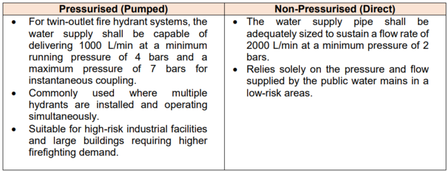
Regarding external hydrants, there are pressurised and non-pressurised types. The following table outlines the differences between these two types of external hydrants:
HYDRANT PUMP
Hydrant pumps draw water from the fire water storage tank using two sets of pumps, one duty pump (electric) and one standby pump (diesel). The functions of the pumps are as follows:
- Jockey Pump: A small pump that maintains a stable water pressure in the pipeline at all times and prevents the main pump from continuously switching on and off due to minor leaks.
- Duty Electric Pump (Electric Pump): A high-capacity pump that automatically starts when the water pressure drops below a predetermined level, indicating a fire hydrant is in use.
- Standby Diesel Pump (Diesel Pump): An emergency pump that automatically takes over in the event of a power failure.
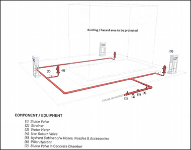
Figure 1: Typical Arrangement of Direct Fire Hydrant System [1] 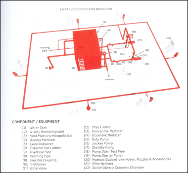
Figure 2: Typical Arrangement of Pressurised Fire Hydrant System [1] 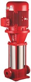
Figure 3: Jockey Pump in External Fire Hydrant [2]
For high-risk buildings, the hydrant pump shall be capable of delivering 2000 L/min at a minimum pressure of 4 bar to any pair of twin outlet hydrants operating simultaneously. The standby pump shall remain operational during power failure conditions through either emergency generator or diesel engine drive. The emergency generator must have sufficient capacity to power the hydrant pump for at least 2 hours. In addition, electrical cabling supplying power to the hydrant pump system should be of the fire-rated type to ensure continued operation during fire conditions. Where emergency generator supply is unavailable, the standby pump is typically driven by a diesel engine. The diesel engine must be capable of operating continuously at full load for 2 hours using diesel fuel and must be designed to operate under varying load conditions. Diesel engines must be equipped with an integrated constant-speed governor to maintain the rated pump speed under varying load conditions.
Fire safety standards impose strict requirements on the diesel engine, battery, starter system, and pump room arrangement. The battery capacity and starter motor for the diesel standby pump must be sufficient to provide six starting cycles. Every starting cycle requires the starter motor to crank for at least 15 seconds, followed by a rest period of no more than 10 seconds between attempts. The diesel engine shall start successfully by the seventh starting cycle. Furthermore, batteries for diesel-driven standby pumps are typically of the maintenance-free type to improve reliability. Additionally, the fuel supply must contain sufficient diesel to allow the engine to operate at its maximum load for a minimum of two hours. In addition, electrical cabling supplying power to the hydrant pump system should be of the fire-rated type to ensure continued operation during fire conditions.
A small jockey pump, usually driven by an electric motor with a capacity of approximately 120 L/min, is installed to automatically restore pressure lost due to minor leaks. This ensures stable pressure within the piping system and prevents unnecessary activation of the main pump, which could otherwise result in unnecessary pump operation or electrical tripping.
The pump room shall incorporate several protective measures to ensure reliable operation during emergencies. It shall be protected from rain and located away from flood-prone areas. Adequate natural or mechanical ventilation shall be provided, and the room shall be clearly labelled with appropriate safety signage. A portable carbon dioxide (CO₂) fire extinguisher shall be provided within the pump room for electrical fire protection.
HYDRANT TANK
The minimum effective net capacity required for the fire storage tank is 67.5 m³. Together with an automatic refill flow rate of 500 L/min, this capacity is generally sufficient to support 45 minutes of hydrant pump operation. For larger hydrant systems, a greater storage capacity may be required, with effective tank capacities of up to 108 m³ commonly used for higher firefighting water demands. Besides, a four-way breeching inlet is commonly provided to enable BOMBA to replenish the fire water tank during prolonged firefighting operations.
Therefore, for the completed structure, the tank shall be designed to accommodate 108 m³ to ensure a reliable water supply. The effective usable tank capacity shall not be less than 67.5 m³. The usable capacity of the tank is defined as the volume of water between the normal water level and the low water level (LWL), which is set at 600 mm above the highest point of the pump suction pipe outlet or at the top of an approved vortex inhibitor flange. This arrangement prevents air entrainment and vortex formation at the pump suction inlet.
Typically, fire water storage tanks are separated from domestic or other non-firefighting water storage systems. However, in some cases, they may be combined with water storage for other fire suppression systems. In such instances, the combined tank capacity must be sufficient to meet the total water demand of all connected fire protection systems.
Furthermore, fire water storage tanks are commonly constructed using pressed steel, reinforced concrete, or fibreglass reinforced polyester (FRP), depending on project requirements and environmental conditions. Large fire storage tanks are often compartmentalised to facilitate maintenance while maintaining continuous water availability for firefighting operations.
PUMP START PANEL AND CONTROL
The pump starter panels for the duty pump, standby pump, and jockey pump shall be separated from panels serving other firefighting systems and provided with individual indicator lights and controls to improve operational reliability and prevent failure of one system from affecting the others. The hydrant pumps are designed to start automatically upon activation of the pressure switches and shall also be provided with a manual start capability. Once activated, the hydrant pumps can only be stopped manually. Electrical cabling supplying power to the hydrant pump panels should be of the fire-rated type to ensure continued operation during fire conditions. Meanwhile, the pressure switches are typically installed along the pump discharge or test line to monitor system pressure continuously.
In the event of a fire, a commonly adopted arrangement is:
- Pressure drops to 90%: The jockey pump starts automatically to compensate for minor pressure loss.
- Pressure drops to 80%: The jockey pump stops operating and the duty pump starts automatically, indicating a significant demand for firefighting water flow.
- Pressure drops to 40%: The standby pump starts automatically, typically due to duty pump failure or an exceptionally high firefighting demand.
CONCLUSION
In conclusion, an external fire hydrant system is a critical component of fire protection infrastructure that ensures a reliable and readily accessible water supply during fire emergencies. Proper design, installation, testing and maintenance must be carried out to ensure that the hydrant system remains accessible, visible, and capable of delivering the required flow rate and pressure in accordance with MS 1489 and UBBL 2021. This ensures the system remains reliable and effective in protecting lives, property, and building occupants during fire emergencies.
Ir. Dr. Justin LAI Woon Fatt
CEO / Founder
IPM Group