Author: Ir. Dr. Justin LAI Woon Fatt | 25 August, 2026
INTRODUCTION
In modern building design, a pressurisation system plays a vital role in fire safety by protecting designated escape routes from smoke infiltration. The system works by supplying fresh air into protected escape paths such as staircases, lobbies, and sometimes corridors, maintaining a higher air pressure in these areas compared to adjacent occupied spaces. This positive pressure difference prevents smoke from entering these crucial evacuation routes, allowing occupants to evacuate safely during a fire emergency.
PRESSURISATION SYSTEM REQUIREMENTS IN MALAYSIA
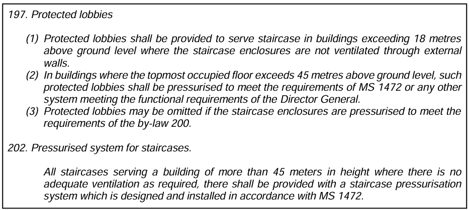
Although pressurisation systems are essential in many buildings, they may be omitted if natural ventilation within the protected escape routes meets regulatory requirements, such as those outlined in the Uniform Building By-Laws (UBBL) 1984 (Amendment 2021) (specifically By-Laws 197 and 202) or equivalent standards. When installed, the system design must comply with applicable codes such as MS 1472, AS1668, and UBBL to ensure effectiveness and safety [1].
Below are the By-Laws 197 and 202, stating about protected lobbies and pressurised system for staircases in the UBBL 1984 (Amendment 2021) [2]:
METHODS OF PRESSURISATION
Pressurisation systems vary depending on building layout and complexity. Common design approaches include [1]:
1. Staircase Pressurisation
The simplest method involves pressurising only the staircase, which is effective when the staircase opens directly into accommodation areas or simple lobbies. Each stairwell requires an independent pressurisation system to maintain a pressure differential of approximately 50 Pa higher than adjacent occupied spaces. The system must provide an egress air velocity of at least 1 m/s when doors are open to resist smoke inflow.
2. Staircase with Lobby Pressurisation
For buildings with more complex layouts, pressurisation extends to both the staircase and the lobby. In this setup, the lobby is pressurised separately but maintained at a pressure roughly 5 Pa lower than the staircase. This creates a controlled airflow from the staircase through the lobby, preventing smoke ingress while maintaining safe evacuation paths.
3. Staircase with Lobby and Corridor Pressurisation (Smoke Extraction in Corridor)
In cases where corridors form part of the protected escape route and have a fire resistance rating of 30 minutes or more, these corridors must also be pressurised or alternatively equipped with smoke extraction systems. The corridor pressure is maintained below the staircase pressure but above the pressure in the adjacent accommodation areas, establishing a pressure differential that helps prevent smoke from entering the protected escape route. These layered pressurisation strategies help effectively compartmentalise the building’s escape routes and limit the spread of smoke during fire events.
HOW THE SYSTEM WORKS
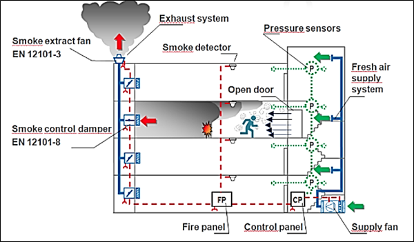
Under normal operating conditions, the building runs on its main electrical power supply. The generator remains on standby and is not operating, with diesel fuel safely stored in its tank, ready for emergency use. During this period, the pressurisation fans are typically switched off or operated periodically in test mode to ensure system readiness. Meanwhile, the control system continuously monitors temperature and smoke detectors throughout the building, ensuring that any signs of fire or abnormal conditions are detected immediately for prompt response.
However, in the event of a power interruption or fire emergency, the system automatically transitions from normal operation to emergency mode to ensure continuous power supply and effective smoke control by going through the following steps:
1. Fire Detected
When smoke or heat is detected, the fire alarm system is immediately triggered, alerting the building’s fire control panel. The control panel then sends a signal to activate the pressurisation fans, initiating the process of supplying fresh air to protected escape routes such as staircases and lift lobbies. At the same time, the system prepares the standby generator to start automatically in case of a power failure.
2. Power Failure Occurs
When the Automatic Transfer Switch (ATS) detects a loss of the main electrical power supply, it immediately initiates the automatic switching process from the lost main power source to the generator [3]. Within a few seconds, the generator automatically starts by drawing diesel fuel from the storage tank. The generator then accelerates to its designated operating speed and stabilises, ensuring a steady and reliable power output.
3. Generator Powers Emergency Circuits
The Automatic Transfer Switch (ATS) transfers the building’s essential load from the main power supply to the generator. At this stage, all critical systems, including the pressurisation fans, fire pumps, emergency lighting, and fire alarm systems, receive power directly from the generator.
4. Fans Pressurise Escape Routes
The pressurisation fans draw in fresh air from outside and deliver it into staircases or lift lobbies through a network of ductwork [4]. Pressure sensors continuously monitor the pressure within these protected areas to maintain the required pressure differential between the escape routes and adjacent spaces. Control dampers automatically regulate the airflow to maintain the required pressure, typically around 50 Pa. If the pressure becomes too high, pressure relief dampers automatically release the excess air to prevent excessive pressure from making doors difficult to open.
5. System Runs until Fire is Cleared
The generator continues to operate by drawing fuel from the diesel tank. The emergency power arrangement shall be capable of maintaining the operation of essential fire safety systems for the required emergency duration. Once the main power supply is restored, the Automatic Transfer Switch (ATS) automatically transfers the electrical load back to the normal grid supply, and the generator gradually shuts down, returning to standby mode.
STACK EFFECT IN TALL BUILDINGS
In tall buildings, the natural pressure difference between the interior and exterior of the building can influence the performance of a pressurisation system. This phenomenon, known as stack effect, occurs because of differences between indoor and outdoor air temperatures [5]. Depending on the temperature relationship, airflow may be driven upwards or downwards through vertical shafts and other leakage paths.
This can affect the pressure differential within staircases and protected lobbies, particularly where the pressurisation fan serves a tall vertical shaft. Unmanaged stack effect can defeat a high-rise building’s smoke controls, blocking escape routes and hindering fire rescue teams [5]. The effects of stack and reverse stack conditions should therefore be considered during system design and performance assessment.
TESTING, COMMISSIONING & PERFORMANCE VERIFICATION
Before system handover, comprehensive testing and commissioning procedures are required to confirm performance.
-
- Pressure tests verify duct integrity and ensure leakage is within acceptable limits [1].
- Balance or flow tests at supply outlets confirm design airflow distribution.
- Performance simulation: one or more doors are opened to simulate fire conditions, measuring airflow and pressure differentials to verify that smoke ingress is prevented under design conditions.
- Visual and mechanical inspections are required to check dampers, fan installation, wiring, control logic, duct routing, and installation quality.
- The commissioning checklist confirms compliance with the design specification, emergency power integration, and operator instructions.
CONCLUSION
In summary, a pressurisation system in a building is a critical component of modern fire safety engineering, especially in buildings with multiple floors and complex egress paths. By maintaining positive pressure in escape routes such as staircases, lobbies, and corridors, it prevents smoke infiltration and enables safer evacuation. Successful implementation demands careful design, meticulous installation, and thorough testing to ensure the system performs as intended under fire conditions. Given the complexity and the need to interface with architectural, mechanical, and fire engineering systems, engaging a specialist fire safety consultant is strongly recommended to ensure code compliance, optimal performance, and occupant safety.
Ir. Dr. Justin LAI Woon Fatt
CEO/ Founder
IPM Group