Author: Ir. Dr. Justin LAI Woon Fatt | 23 February, 2026
INTRODUCTION
Carbon dioxide (CO2) extinguishing system comprise of CO2 cylinders, steel piping, discharge nozzles, heat and/or smoke detectors, and a control panel that monitors the protected area and activates both visual and audible alarms prior to gas discharge. When a fire is detected, CO2 is discharged after a time delay to alert any occupants to evacuate the room. CO2 extinguishing systems are typically provided for electrical transformer rooms, switch rooms, and standby generator rooms. In addition, a CO2 extinguishing system should not be installed in normally occupied rooms.
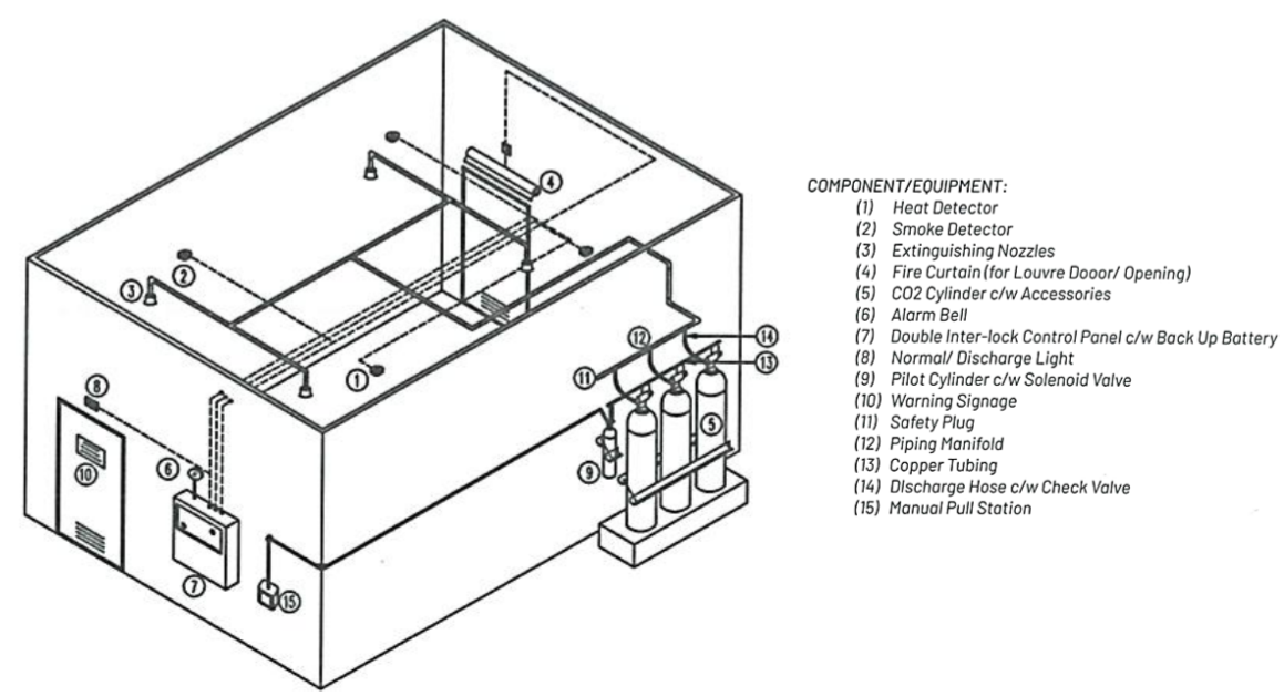
Figure 1: Carbon Dioxide Fire Extinguishing System Typical Arrangement Drawing [1]
CO2 FIRE EXTINGUISHING SYSTEM DESIGN
The Uniform Building By-Law 235 1984 (Amendment 2021), states that fixed extinguishing systems shall either be total flooding system, or local application systems, depending on the nature of the hazard, process, and occupancy, as required and approved by the Director General (DG) of the Fire and Rescue Department of Malaysia (FRDM). The applicable standards for CO2 extinguishing systems are NFPA 12 and MS 1590 [1].
The CO2 extinguishing system is designed to achieve a 50% flame-extinguishing concentration of CO2 at 21 °C. CO2 should discharge fully under 1 minute for surface fires. For deep-seated fires, the total discharge shall not exceed 7 minutes or 30% concentration discharge within 2 minutes [1]. A 40% increase in design quantity of CO2 is required for local applications using high-pressure storage, as only the liquid portion of the discharge is effective [1]. The CO2 extinguishing system shall be based on total flooding principle and/or local application with time delay period of 30 seconds, adjustable up to 60 seconds maximum [1]. All components must be located, installed or protected from mechanical, chemical or other damage, while all devices for shutting down supplementary equipment shall be integrated with system and function with system operation [1].
The CO2 system is powered by a 240 V AC, 50 Hz mains supply, in addition, the control panel charges a 24 V DC standby maintenance-free battery for automatic backup during outages / main power supply failure, and provides visual and audible fault indications [1]. The standby battery shall be trickle charged in normal operation. In addition, the area shall be protected with two or more heat or smoke detectors, and activation of the detectors shall be indicated through illumination of indicator light and audible warning sound. At least two of detector zones must be activated in order for the system to discharge CO2 automatically. Meanwhile, manual activation of CO2 system shall be provided through a “break glass” handle type manual pull box, mounted outside the exit door to protected space. With regards to maintenance, the detector wiring shall be continuously supervised, with faults and disconnections in the wiring / circuit indicated by a panel / fault lamp and a buzzer.
STORAGE AND COMPONENTS
A CO2 extinguishing system is designed to hold liquefied CO2 at ambient temperatures in either low-pressure (2068 kPa, refrigerated, liquefied form) or high-pressure (5171 kPa, ambient temperatures) cylinders, with high-pressure [1]. Typically, ambient temperature storage is often preferred for cost efficiency, as it is mostly impractical to have an additional refrigeration system in place, which adds an additional maintenance item to be monitored. Cylinders shall be rated at 59 bar (at 21 °C), tested to 228 bar pressure, must have quantity indicators, permanent labels (which specifies number, filling weight and pressurisation level of cylinder), and be uniform in size if distributed by the same manifold [1]. In addition, in systems where more than three cylinders are required, a pilot cylinder shall be provided to activate the discharge from each cylinder. Each is equipped with a solenoid-operated discharge valve to discharge CO2 at required rate, with internal dip tubes extending to the bottom of the cylinder to permit discharge of liquid CO2, for containers with top-mounted valves. Furthermore, cylinders should be located outside the hazard area with adequate protection against vandalism.
A control panel shall display system status, hazards, faults, and provides alarms for discharge, pre-discharge, and fault conditions, alongside device for shutting down exhaust fans and activating solenoid powered curtains, in addition to complying with MS 1404 [1]. Alarms indicating failure of supervised devices should be distinct from alarms indicating operation of the system, or hazardous conditions. In addition, a discharge pipe pressure switch shall be provided to provide signal back to the control panel, that the CO2 gas has been discharged.
On the other hand, CO2 discharge nozzles must meet minimum discharge pressures, be corrosion-resistant, and be clearly marked for identification and display equivalent orifice diameter, regardless of shape and quantity and nozzles. Discharge nozzles shall be consist of the orifice and any associated horn, shield or baffle. Nozzle pressure should be 1034 kPa for low-pressure storage, while for high-pressure storage, nozzle pressure should be 2068 kPa [1]. Furthermore, for areas with high-risk of debris clogging or high dust environment, discharge nozzles should also contain frangible discs or blow-out caps to prevent clogging by foreign elements.
Automatic detection and alarm bells should be triggered by corrosion-resistant heat or smoke detectors, with alarms producing at least 65 dB or 5 dB above the ambient sound level, whichever is higher, powered by the fire alarm battery [1]. In addition, the bell should be of trembling type, and not single-stroke type. Meanwhile, the CO2 piping and fittings should be made of non-combusting material, have the ability to maintain its own shape during the outbreak of fire, and be compliant with API Schedule 40 steel for low pressure storage systems. On the other hand, for high-pressure CO2 system, the CO2 piping system should be compliant with Schedule 40 for pipes with 20mm diameter and below, while for pipes with 25mm diameter and above, the pipes should be compliant with Schedule 80 [1]. Flexible piping, tubing or hoses (including connections) utilised should be able to withstand the rated pressure of the system. Furthermore, warning signs are required at all entrances and within protected areas at prominent and highly visible locations.
APPLICATIONS
CO2 fire extinguishing systems are widely used for their rapid action, residue-free results, and highly effective fire suppression capabilities where other fire suppression methods may result in water, chemical or residue damage. Key applications of CO2 fire extinguishing systems include [2]:
- Sensitive environments – Data centres, archives, and museums where equipment, documents, and artefacts require protection from water or chemical damage.
- Industrial facilities – Areas handling flammable materials, hazardous goods warehouses, turbines, transformers, and specialised metal processing systems.
- Marine industry – Ship engine rooms and offshore platforms, where confined spaces require effective, non-water-based suppression.
- Power generation – Electrical cabinets, rooms, generators, and substations to ensure uninterrupted power supply and prevent secondary damage.
- High-risk zones – Paint booths, powder-coating rooms, hydraulic systems, cable shafts, silos, dust filters, and printing machinery.
SAFETY PRECAUTIONS
CO2 fire extinguishing systems require strict safety measures to protect both people and property. Since CO2 suppresses fire by reducing oxygen levels, accidental exposure in confined spaces can lead to serious health risks, such as unconsciousness and asphyxiation, which can even lead to fatalities [3]. To prevent this, CO2 fire extinguishing systems should be equipped with alarms, time delays, and clear evacuation protocols to ensure all personnel exit before discharge.
Access to protected zones must be restricted during discharge, and only trained personnel should operate the system, or supervise re-entry. Routine inspection and maintenance of cylinders, valves, detectors, and piping are essential for reliable performance. After activation, ensure proper ventilation to remove residual CO2 before re-entry. Warning signs and safety notices must be prominently displayed to highlight potential hazards.
CONCLUSION
In summary, a CO2 extinguishing system offers a fast, effective, and residue-free method of fire suppression, making them ideal for safeguarding sensitive equipment, critical infrastructure, and high-risk industrial environments. Their ability to suppress fires rapidly without causing water damage helps preserve valuable assets and minimise operational downtime. However, because CO2 works by displacing oxygen, strict safety protocols, proper system design, and regular maintenance are essential to ensure both system effectiveness and occupant safety.
Ir. Dr. Justin LAI Woon Fatt
CEO/ Founder
IPM Group